
تبلیغات

موضوعات

جستجو

پیوندهای روزانه

لینک دوستان
- دریافت رایگان این قالب
- سایت عاشقانه ماندگار فان
- سایت عاشقانه عشق آفرین
- جامعه رادیو اماتوری ایران
- سازمان تنظيم مقررات و ارتباطات راديوئي
- شرکت اروم الکترونیک
- فروشگاه قطعات الكترونيكي
- ARRL • Devoted Entirely to Amateur Radio
- درددل های یک بازنشسته
- نخستین سایت آموزشی رادیو آماتوری در ایران
- نشریات آماتوری
- EP2MRD
- QRZCQ - The database for radio hams
- شناسه تخصيص نحوه دستورالعمل ايستگاه به ارتباط راديويي هاي ) Call Sign ( دستورالعمل ارتباط شناسه تخصيص نحوه ايستگاه به راديويي
- رادیو آماتوری
- کلوپ رادیو آماتوری ایرانیان
- ارسال لینک

صفحات جانبی

امکانات جانبی
 آمار
وب سایت:
بازدید دیروز : 4985
بازدید هفته : 22790
بازدید ماه : 40256
بازدید کل : 2215548
تعداد مطالب : 673
تعداد نظرات : 121
تعداد آنلاین : 1
20m Loop Antenna
by Harry Lythall - SM0VPO

Introduction
I recently saw that my 80m (3.5MHz) loop (or frame) antenna has been really popular, and that there are loads of other radio amateurs who have taken my design and "ran with it" to produce variations that all have some great improvement. There have been many in-depth tests and simulations, all with exceedingly good results and reports. This is exactly what I am aiming for with my homepages - free information for all and my designs being improved upon. That way we all win :-)
One small point all varaitions have in common is the need for an expensive tuning capacitor and a very restricted RF power level. Of course, you can throw money at the problem, but for me this hurts. I got to thinking that there must be a way of adjusting the design a little and finding another technique to tune the antenna, and to make the best use of the little radio transciever I have in Sweden, given the limited space.
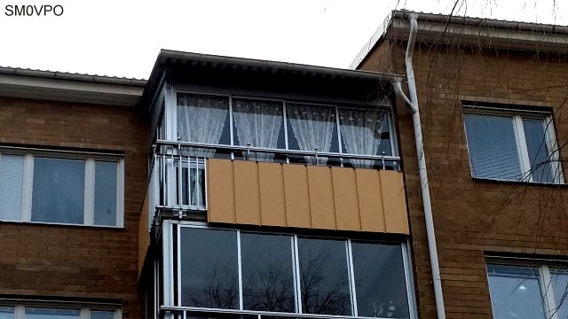
My limited space apartment.
As you can see there is not much opportunity for grand antennas. And to add to this, the equipment I have in Sweden is also limited to a single 5-Watt unit.
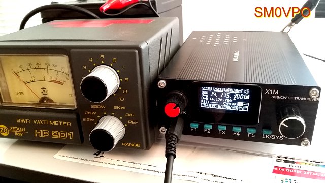
My limited equipment - only 5-Watts.

The Design Thoughts
Today I have no area of land to use for antennas. I have a glassed-in balcony on the 4th floor of an apartment block. I really like the 20m (14MHz) band so I will concentrate on that. I am not really interested in the CW end of the band, except perhaps 14.070MHz for the digimodes. So my requirements are:
- As efficient as possible (useable)
Total price less than $2
The antenna I have created is based on my original 3.5MHz loop (or frame) antenna. This time I built it out of scrap components. I cadged (tiggade) some plastic conduit tubes from an electrical contractor at work. The same guy also gave me the remnants of a roll of 2.5mm C.S.A. multi-strand mains cable. That was all I needed.
In my junkbox I found no tuning capacitors, but WAIT!! Why do I need to tune the antenna? Once it is tuned I should not need to tune it again, just set the centre-frequency to 14.175MHz. If I can get the Q-factor to around 100 then my useable 3dB bandwidth should be more than 150kHz. That will give me 14.10MHz to 14.25MHz.
Ok, I need a 1-off, preset tuning capacitor. Why not use a Gimmik Capacitor? Just twist two bits of wire together and cut it short to get the resonant frequency I want. So I need to get the coil wound so that there is sufficient cable length and self capacitance to give a resonance of about 14.5MHz without any extra capacitance what-so-ever. That means I need just a few pf. That sounds like a good plan.

Construction
The 15mm Diameter plastic tube I "aquired" were 80cm long. After much trial and error I found that exactly 3 turns, with 2.5cm spacing, gives about 14.9MHz self resonance. The wire support holes are exactly 4cm spaced, beginning 1cm from the end of each tube. The two tubes are fixed into a and X using zip-straps (tie-wraps, buntband). The feed loop is 1/2 turn.
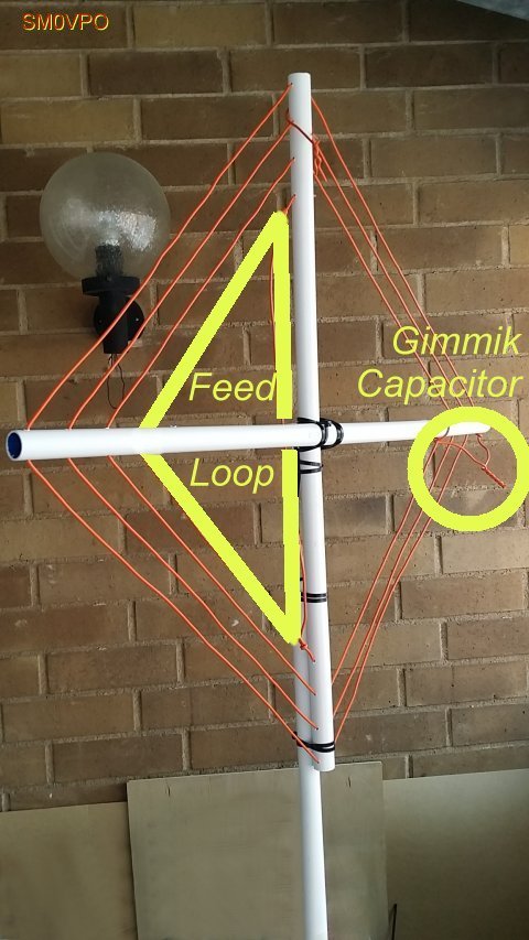
Note the size and position of the feed loop. Also the Gimmik capacitor.
One problem I had with the original loop antenna was that of RF coming back down the cable braid. Using on old FT-101ZD it was possible to feel the RF on the microphone with your lips. The cure for this is to use a balanced feed and at least 5m of RF cable.
I robbed the ferrite ring for the balun from an old ATX computer PSU and made a triflar wound torroidal transformer. That is to say, twist together three lengths of 1mm x 7-strand insulated hookup wire together. Use this to make a 7-turn coil and connect the three coils in series, with four connections. Feed connections (numbered in the picture below) 1 and 3 are connected to to the antenna feed loop. Connect the coaxial cable braid to connection 2, and the coax centre to connection 4. My balun is self-supported on the connection leads.
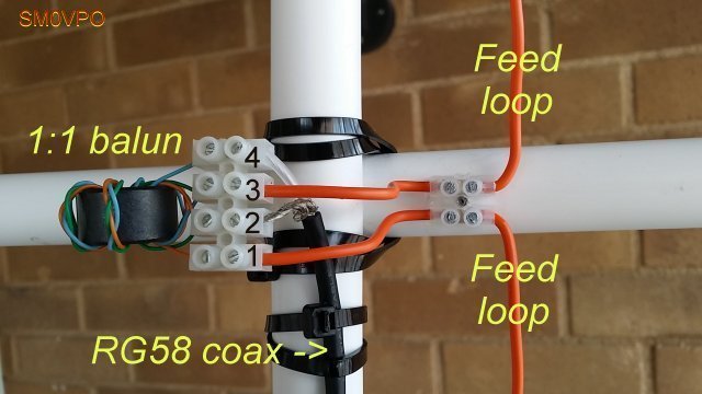
The 1:1 Balun I used.
The coaxial feed cable was found to affect the resonance slightly, so I fed that through an extra bit of tube to make it stay in one place. It works fine.
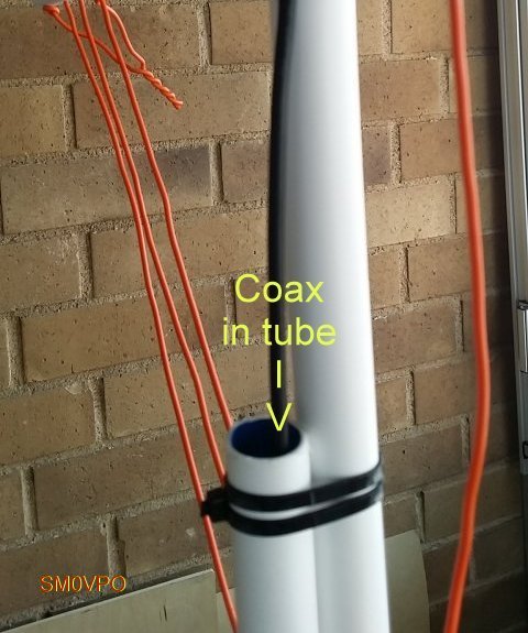
Feeder cable secured in the support tube.

Testing
Testing is very easy. I used my GDO-2 to check the middle-turn of the loop for a dip. Twist the two tails together to form the Gimmik capacitor and adjust the length of the twist until the centre-frequency is 14.175MHz. With the GDO you can get it within about 100kHz to 200kHz, but then you can check the VSWR using your HF radio. You can also sweep the band for maximum noise and get a very close approximation.
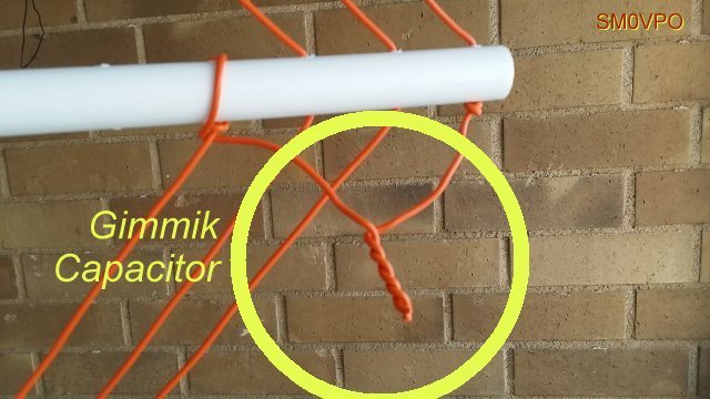
The Gimmick capacitor.
The centre.frequency of my 20m Loop antenna is 14.175MHz, and the VSWR is better than 1.05:1 (I can hardly see any movement on my meter). The Q-factor is somewhere aproaching 100. The useable bandwidth is just a little narrower than I would have wished, but the antenna certainly works well and meets all the other criteria. But the slightly less useable bandwidth criterion is at the expense of better performance, and it still allows me to use 14.070MHz, although it is a little quiter down there.
| Frequency | VSWR |
|---|---|
| 14.010 | 3:1 |
| 14.095 | 2:1 |
| 14.130 | 1.5:1 |
| 14.175 | 1:1 |
| 14.220 | 1.5:1 |
| 14.260 | 2:1 |
| 14.325 | 3:1 |
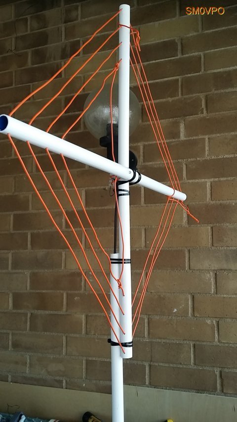
The completed antenna.

Conclusion
No-matter how you play with the figures, the best indoor antenna cannot replace a full-size dipole antenna. But the indoor antenna can give some extra features, such as just reaching out your arm and trimming a little, which you cannot do with a long-wire antenna up a tree out in the garden, especially when it is raining.
This antenna gets me on the air on 14MHz, and it has a useable frequency range. The VSWR is almost perfect at the centre-frequency, and this time I don't burn my lips on the microphone (not that I am likely to do so with just 5-Watts of power). The design uses no expensive components, in fact the only item I bought was the block-connector for the balun. That cost me US$1.50 for a pair of 12-contact screw-terminals. The construction is ridiculously simple and easy to build.
On the air I can hear traffic on 14.070 digimodes, and from 14.130 to 14.220MHz I have a near-perfect VSWR aqnd good clear reception of SSB. I can also rotate the antenna to cut out rubbish, and most of all, using the Gimmik capacitor I don't need to re-tune it: it seems temperatore-stable. The weight is less than 500g and when I poke it out of the balcony window the reception improves, the VSWR does not change, and I can make myself heard among the big boys.
I hope that you have some fun building and using this antenna. If you have any ideas for further improving it then please use my forum.

Dont forget to visit my messageboard if you have any questions about this or any other project. I always look forward to receiving feedback, positive or negative.
Very best regards from Harry Lythall
SM0VPO (QRA = JO89WO), Märsta, Sweden.
EA/SM0VPO (QRA = IM86BS), Nerja, Spain.
- Small size, also portable so I can use it for field use
- No expensive components, everything available locally
- No TVI, QRM or interference to stereos or computer sound

ورود کاربران

عضويت سريع

پشتيباني آنلاين

آمار

خبرنامه

آخرین نطرات کاربران
 جواد یاور مطلق - درود
 بلا بدور باشه مهندس !
انشالله همیشه سرحال سالم تندرست باشید !
پاسخ:با درود و سپاس از لطف شما دوست گرامی بدرود - 1403/1/29
 یک هم وطن - من بدون مدار این رادیو ساختم باصدای واضح و بلند بدون برق و باطری
 پاسخ:باتشکر از لطفتان امیدوارم بقیه دوستان هم همت کنند و دست به اچار و هویه شده خودشان بسازند و لذت ساختن را ببرند چون در داشتن لذت نیست هنر ساختن است - 1402/6/13
 AEC - درود
استاد ممنون خیلی خوب و عالی
پاسخ:باسلام و تشکر از لطف و مرحمت شما دوست عزیز و گرامی - 1400/8/28
 پرویز مهرزاد - سلام ودرود استاد عبدالحق عزیز بسیار خوشحالم که سایت جنابعالی بامطالب جدید وعالی دوباره فعلیتش را شروع نموده است.
پاسخ:با سلام تذکر بجا و بموقعی بود بسیار متشکرم - 1400/8/28
 ایزدی - یه مشکلی داره این طرح. کل سلف ها با هم 12. 7 میکرو میشه که با خازن 270 پیکو، فرکانس مرکزی فیلتر 2.7 مگا هرتز می شه. کمترین سلف هم (0.1 میکرو) با همون خازن 270 پیکو 30 مگاهرتز رو رد می کنه. بنا بر این نیازی به خازن های دیگه نیست. دوستان دیگه نظرشون چیه.
پاسخ:باسلام و تشکر کل خازن ها و سلفها برای فرکانس 1800کیلو که ابتدای باند رادیو اماتوری است کم است و بسختی تنظیم می شود اما برای 3500 بله زیاد است - 1399/8/24
 هومن - سلام .علت استقبال نکردن در خور توجه همین نا واردیست .این مطلب بسیار گنگ و پر از اشتباه هست
 پاسخ: سلام بنده هم ضمن تائید نظر شما درخواست می کنم مطلب کامل تر و بهتر و درست تر را بفرمائید بنده بنام خودتان درج و منتشر نمایم
پاسخ:https://t.me/joinchat/AAAAAEJj30AwLGIyi_UQ3g مدارات لامپی - 1396/12/17
 علی - سلام شما مکتبی و انقلابی هستید درسته ؟
پاسخ: سلام بهیچ عنوان و تقریبا هیچ جائی من چنین ادعائی نکرده ام اما این همه شهید و زخمی و جانباز و اسیر و زحمت و فعالیت برای حفظ انقلاب و سرزمین عزیزمان ایران خیلی حرام لقه گی و بی اصل و نصبی می خواهد که چشم خودرا ببندیم و از این اب و خاک حمایت و به این مردم عشق نورزیم حالا شما اسم انرا هرچه دوست دارید بگذارید نظرتان محترم است - 1396/12/17
 هومن - سلام
 بنده یکی از علاقمندان لامپ هستم . و 10 سال اخیر را بر روی مدارات لامپی کار کردم .با سرچ اینجا را پیدا کردم .می خواستم ببینم در زمینه مخابرات فعالیت لامپی در ایران هست ؟
این مطلب راجب لامپ واقعا توجه مخاطب علاقمند را جلب می کند ؟
من فکر می کنم نویسنده اصلا راجب لامپ حس خوبی ندارد .عذر خواهی می کنم
پاسخ:سلام دوست عزیز از صراحت و فصاحت بیان شما خوشحالم مطلبتان راجع به نویسنده مطلب لامپ کمی کم لطفی و شاید سخت گیری در بر دارد نویسنده مطلب استاد عاملی بزرگ رادیو اماتوری ایران هستند و مطلب را بی اندازه ساده و اسان گفتند چون اکثر جوانها از لامپ و ولتاژ کار ان وحشت داشته و تقریبا هیچ نمی دانند اما ظاهرا شما در مورد لامپ مطلع و ازموده هستید لذا برخود نگیرید شما هم اگر در مورد لامپ و یا مطالب استاد عاملی نقد و نظری دارید بسیار خوشحال می شوم مکتوب بفرمایید تا در همان بخش یا در بخش جدید بنام خودتان منتشر شود
پاسخ:https://t.me/joinchat/AAAAAEJj30AwLGIyi_UQ3g - 1396/12/16
 سعیدی - سلام استاد بنده بی جواب ماندم
 پاسخ:با سلام و پوزش از تاخیر طبق تجربه دوستان این مدار به دلیل نامرغوب بودن قطعات نو موجود در بازار معمولا در ابتدا کار نمی کند لذا بتوصیه استاد عاملی بهنر است از قطعات اوراقی رادیو و ضبط ها استفاده شود قطعات معمولا در گیر این رادیو ابتدا ای سی سویچ یا کلید زنی است که یک مدل خاصش برای مدار مناسب است و مدلهای دیگر فرکانس کار و ولتاژشان مناسب نیست درمورد ای سی مدولاتور و دمدولاتور 3028 این ای سی هم بشدت مورد شک و شبهه است در موردی باتعویض 5 عدد ای سی دو عدد که بهتر بود در مدار بکار گرفته شد لذا بهترین روش استفاده از مرحله مرحله و گام بگام کار کردن رادیو است ضمن انکه اگر فرستنده کار بیفتد گیرنده هم کار خواهد کرد و بالعکس لذا شما می توانید مدار را از میکروفون در حالت فرستنده یا بلندگو در حالت گیرنده شروع نمایید و اگر مسیر سیگنال جدا باشد در نقشه شما می توانید از تقویت صدا شروع کرده و به دمدولاتور رفته و سپس به فیلتر و بعد میکسر وی اف او و در اخر به فیلتر تنظیم باند بروید و حد اکثر سیگنال و حساسیت را بدست اورید پس فیلتر های رادیویی یا بقول شما توکو ها قسمت اخر تنظیم و تعقیب مدارتان است اگر شد برای اطلاع شما و سایر دوستان مدار را در حالت گیرنده و فرستنده جدا اراعه خواهم داد یا با رنگ مسیر سیگنال را جدا می کنم که راحت تر باشد اگر شما عضو تلگرام هستید در یکی از گروه های رادیو اماتوری بیایید و مستقیما با دوستان سازنده و استفاده کننده رادیو تماس گرفته راهنمایی شوید اگر نه ادرس ایمیلتان را بدهید تا راهنمای مونتاژ را برایتان بفرستم
پاسخ:http://py2ohh.w2c.com.br/trx/ararinhamontagem/montandoararinha.htm
راحل مونتاژ و تست مدار است - 1396/11/5
آرشیو
- تير 1403
- مهر 1402
- ارديبهشت 1401
- دی 1400
- آبان 1400
- ارديبهشت 1399
- اسفند 1397
- آذر 1397
- آبان 1397
- خرداد 1397
- ارديبهشت 1397
- فروردين 1397
- اسفند 1396
- بهمن 1396
- دی 1396
- آذر 1396
- آبان 1396
- شهريور 1396
- مرداد 1396
- تير 1396
- خرداد 1396
- ارديبهشت 1396
- فروردين 1396
- اسفند 1395
- بهمن 1395
- دی 1395
- آذر 1395
- آبان 1395
- مهر 1395
- شهريور 1395
- مرداد 1395
- تير 1395
- خرداد 1395
- ارديبهشت 1395
- فروردين 1395
- اسفند 1394
- بهمن 1394
- دی 1394
- آذر 1394
- آبان 1394
- مهر 1394
- شهريور 1394
- مرداد 1394
- تير 1394
- خرداد 1394
- ارديبهشت 1394
- فروردين 1394
- اسفند 1393
- بهمن 1393
- دی 1393
- آذر 1393
- آبان 1393
- مهر 1393
- شهريور 1393
- مرداد 1393
- تير 1393
- خرداد 1393
- ارديبهشت 1393
- فروردين 1393
- اسفند 1392
- بهمن 1392
- دی 1392
- آذر 1392